Networking
Your infrastructure is the foundation your network. Without the correct hardware/software, cabling, network equipment and sufficient power, your systems might not perform as well as you would expect. We do a ground up assessment of your networking infrastructure based upon your business requirements, employee size and growth plans. Our main aim is to help improve your business operations through infrastructure design, implementation and updates. In the first instance contact us using the contact form and highlight your requirements and we will follow up with you on.
Cabling in the Comms Room!
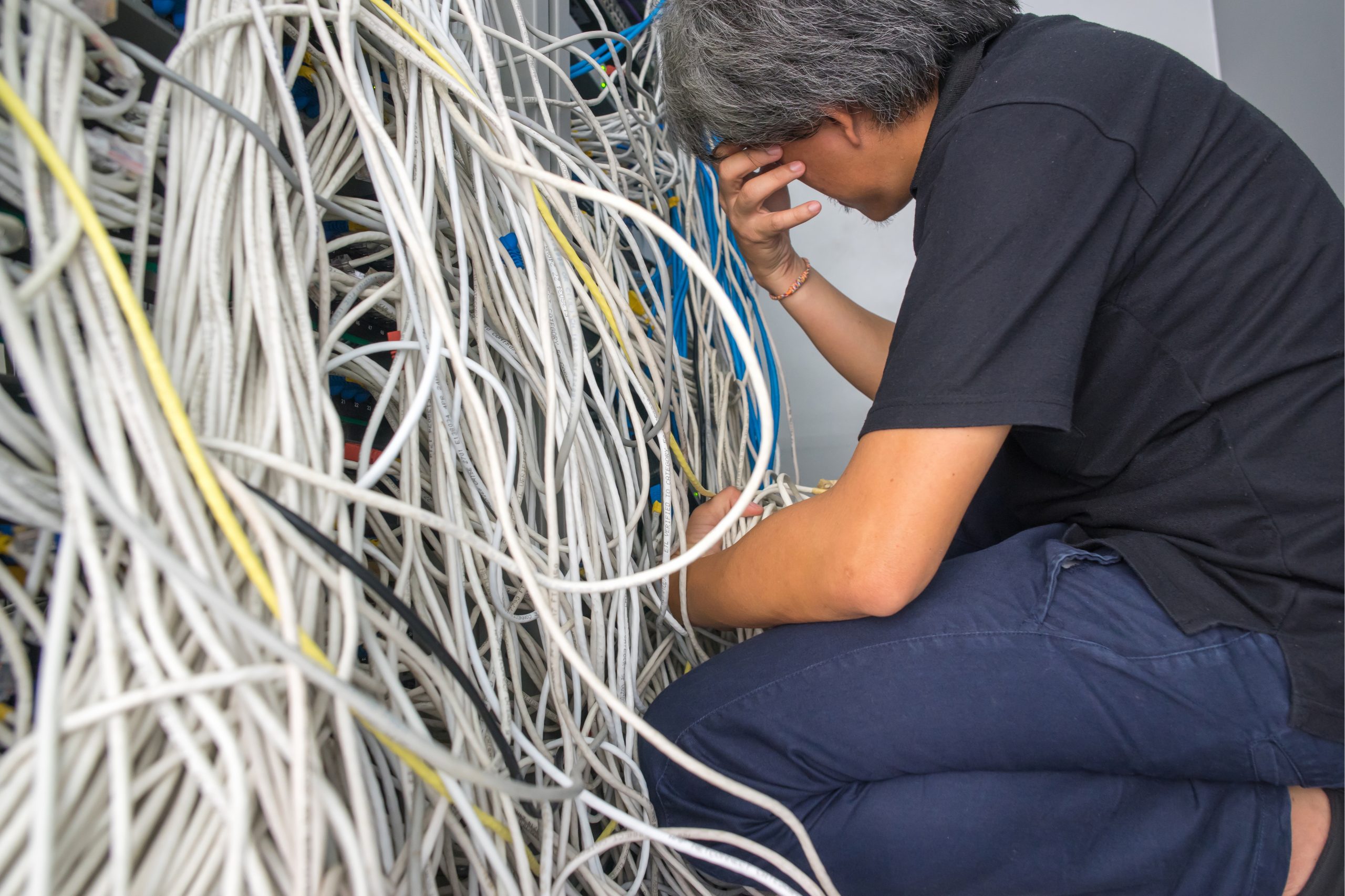
So you need to configure a new phone and you look at the port number then head on down to the Comms room to be confronted by what can only be described as a severe case of spaghetti junction. Head in hands you rummage through the plethora of cables, hoping to be able to find not only the cable in the port you want but where it links to in your switch stack… been there? We can help. In fact if you have any questions or network related jobs that need doing and you need a quote. Head over to our contact page and drop us a line today. We are pretty quick at getting back to you!
Avoid the Spaghetti Stress
The above scenario is most certainly a popular experience from a lot of comms rooms I’ve been in of late. It’s that “oh I’ll just add these three cables in, yeah they are 3m but I can easily trace them”, then another 3 and another 3 and before you know it you have so many cables piled in there that you can’t see either your patch panels or the switch stacks behind them, making it almost impossible to manage quickly and efficiently. If you are feeling the pain right now, no need to panic, we can help straighten things out and get you back on track. Here’s a breakdown of what we do in summary.
Due diligence
First and foremost, we determine which ports are active in both patch panel and switch stacks through assessing device connectivity. This is documented for use later when reconfiguring switches to pass the relevant data.
Remove and Replace
Recable the patch panels and switch connections with an appropriate length cable and where possible using a ‘patch, switch, switch, patch’ mechanism to allow for the smallest cables to be used for tidiness and efficiency.
Documentation
Ideally you will have all this information stored on a spreadsheet showing where each patch panel port is connected and what it does. With the new layout and shorter cables, the documentation adds to the overall manageability
Before a recent job
This was a particularly difficult one to tidy and resolve as the site had only one PoE switch per stack and therefore it was inevitable that there would be the odd long cable to allow connectivity to those devices that needed an injection of power and not wanting to have PoE injectors littering the cab also. So essentially it was a case of locating the rooms to which the ports related to and identify whether or not they were live or not being used. Then determine whether they required PoE (ie Phone or Access Point, CCTV etc.) Then once that was done, the cables that were connected to dead ports could be removed. This clears some of the spaghetti up but still a lot to go. Next is to systematically workout where a cable plugged into a patch panel ends up in the switch and then determine the function of that switch port. Once determined, and documented, the cable is removed clearing more and more space until it is empty. There may be some cables that cannot be removed at this point due to their importance in the building such as CCTV and connections to other cabs or link cables.
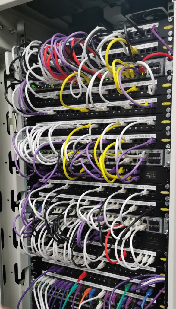
After the job above
In normal circumstances the standard scenario would be to use a patch panel, switch (48port), patch panel setup and cables from the top patch panel would be linked to the top line of the switch and conversely the bottom patch panel would link to the bottom line of the switch. However in this case there were a lot of ports that were not occupied and therefore took the decision to go for a patch, patch, switch, patch patch scenario. The cables were colour coded to represent the function of each. In this example yellow is for Wireles Access Points. Note that the second set of yellow cables connect into a PoE panel to make the whole setup look tidier. As the cables were added each port was configured for the device connected on the other end of the patch panel and subsequently documented as you go along. Once all the cables are restored, the document map showing the connections and functions can be pinned to the cabinet door for easy reference. As you can see from the image to the right, managing the cable is so much easier now and adding new ones is not a fight with the layers of spaghetti of the above image.
Support
We are 24/7 available
There are no restrictions on the times when you can contact us and we operate all year round. Using the contact form will keep a record of the information you need assistance with.


